Constraints in Assembly Design Constraints allow you to position mechanical components correctly in relation to the other components of the assembly. No its not mandatory to publish geometry every time in assembly design.

About Assembly Constraints
Within CATIAs sketching work bench any parallel lines picked for dimensioning will create a linear dimension.

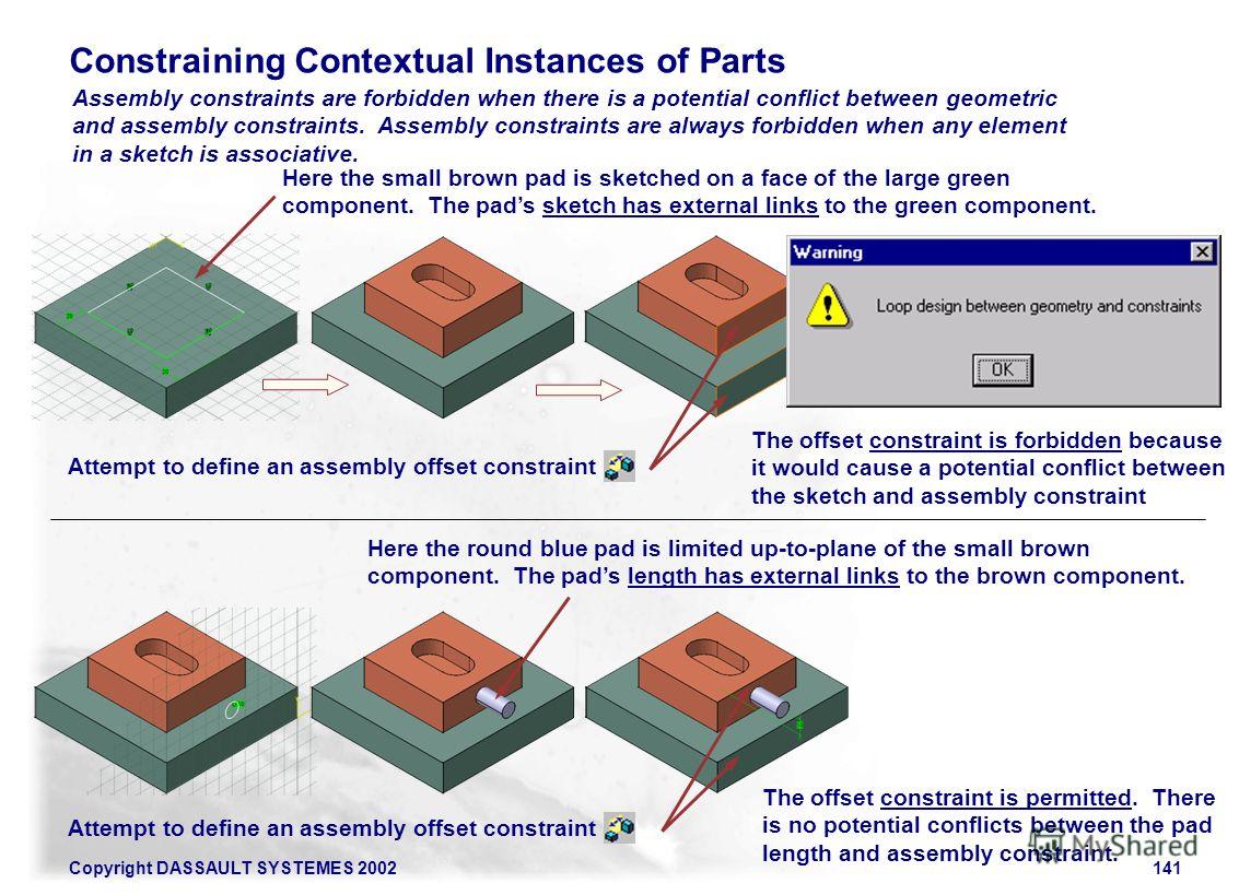
. Loop Design between geometry and constraints Ich habe schon mehrere Elemente versucht es kommt aber immer die selbe Fehlermeldung. The problem was submitted on. The loop is detected when trying to constrain instance of contextual part before the contextual part itself in the CATProduct.
Catia loop design between geometry and constraints Conversely it doesnt signify that If youre able tot build your very own nail artwork you can under no circumstances have Individuals lovable nails. Habe beim erstellen eines Angle Constraint folgende Fehlermeldung erhalten. Inception designs barrel mount.
A warning window opens. Create a linear dimensional constraint between the vertical line and V-Axis as shown in Figure 11. Bitte um Hilfe und Aufklärung des Problemes.
Loop design between geometry and. Loop design between geometry and constraints detected when updating a specific CATProduct. You can either select the geometry or the command first.
The constraint has been created on a level where a bug should allow this creation. Publish command help to reflect same operation to number of part model where as u. Answered on 6 Sep 2017 0346 PM.
In the same way a constraint can not be created. Sketcher constraints - No equal. Catia version 5 release 9.
This constraint can be created between either two elements. This builds a relationship between the constraints. For make constraints geometry you can simply select product from specification tree and than apply existing component from insert menu than constrain it with update.
The code has been enhanced problem conclusion. This video explains ways to use fixed geometric constraint in catia sketcher. Aardvarkdw Mechanical 30 Oct 08 1033.
Loop design between geometry and constraints local fix. Written By curtisuhrich50838 April 07 2022 Add Comment Edit. Select the Constraint Contact icon from the Constraint toolbar Constraint Creation subtoolbar for giving Contact Constraint.
Start the Sketch Module in Catia V5. I would rather have a sketch that clearly shows my design intent ie. Loop design between geometry and constraints 4.
Ferdo posted the following link in the CATIA Forum on Eng-Tips. Click Coincidence Constraint icon in Constraints toolbar then select Line1 in Part1 and Line1 in Part2. But when sketching on a surface of a solid body or maybe on a face It does not snap geometrical constraints from the solid body.
THIS PROBLEM IS PERMANENT RESTRICTION IN CATIA The creation of a coincidence constraint between 2 elements holes from Plate_New and Plate_For_Dist parts is refused due to a loop design between this constraint and geometry on which this constraint lies it means geometrical definition of Plate_For_Dist. Exactly what are Nail Salons for. This is Part 2 of a 5-part article that appeared in the CATIA Operators Exchange COE newsletter back in 2005.
Catia loop design between geometry and constraints. Parallelism geometric constraint in catia sketcher. Again that still clutters the sketch with extra dims.
You just need to specify the type of constraints you wish to set up on one or between two or between three components and the system will place the components exactly the way you want. That several features are equal not that thy just happen to have the same value at this. I am new to Catia V5 and in the process of creating a parametric assembly.
Place the dimension as shown in Figure 10 Step 12. This is one of the many problems I have encountered. I was using this feature in.
The best way to overcome a design loop is not to make reference to any geometry but to define constraints parameters using the other parts parameters you will create an external parameter Rajendra Mathad. This video explains regarding usage of length geometric constraint in catia sketcher. Parallelism geometric constraint in catia sketcher.
As I use the sketcher tool on a plane or a surface it snaps the geometrical constraints from originother linespoints etc while sketching. THIS PROBLEM IS PERMANENT RESTRICTION IN CATIA When updating the product an error message Loop Design is displayed. After deactivating 2 coincidences the update is succesfully done.
Loop design between geometry and constraints the constraint network should be solved. To return the default orientation. Since this thread has had such a high number of reads I wanted to share this information on Links and Design in Context for everyone to read.
These constraints are in priority. Catia Loop Design Between Geometry And Constraints. Any non-parallel lines will create an angular dimension.
This is normal as there is a loop design between the constraint to update and geometry on which it lies contextual part. This video explains ways to create geometric constraint in catia sketcher. Bitte um Hilfe und Aufklärung des Problemes.
Eine Antwort auf diesen Beitrag verfassen mit ZitatZitat des Beitrags IP.

The Optimization Loop Scheme Download Scientific Diagram

About Assembly Constraints

Examples Illustrating Three Types Of Loops A Two Holes On Multiple Download Scientific Diagram
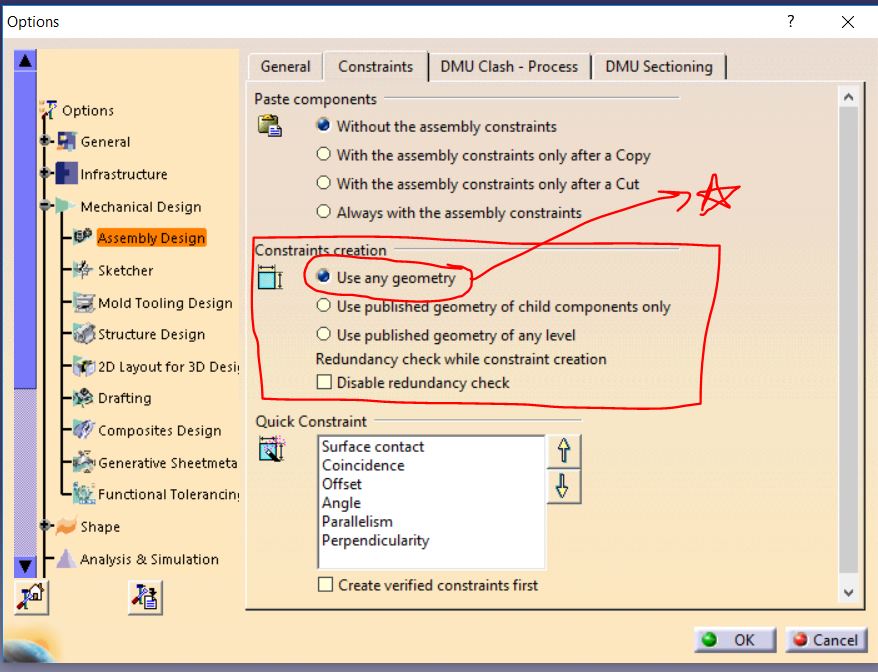
Do We Need To Publish Geometry Every Time While Using Assembly Design In Catia V5 Grabcad Questions

About Assembly Constraints
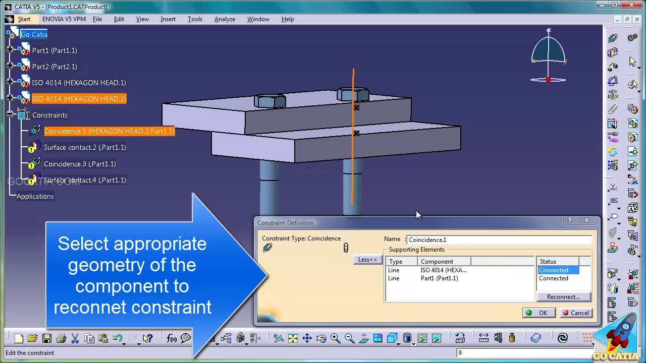
What Does This Error Message Mean During Constrain Attempt Dassault Catia Products Eng Tips
Prezentaciya Na Temu Copyright Dassault Systemes Assembly Design Advanced Catia Training Foils Version 5 Release 8 January 2002 Edu Cat E Asm Af V5r8 Skachat Besplatno I Bez Registracii
Catia Assembly Design Broken Constraints Youtube
0 comments
Post a Comment